Lab Session 1: Introduction to Microcontroller Programming
Estimated time: 1.5 hours (1 session)
Description
The goal of this session is to introduce the fundamentals of microcontroller programming and timing control. We will learn how to configure digital pins, use the Arduino program structure (setup() and loop()), and control LEDs and push buttons with functions such as delay() and millis().
1. Working with Real Hardware
1.1. Prepare the Arduino IDE
Follow the installation steps described in this guide.
Note
Please note that you only need to complete these steps once, and only on your own computer. If you are going to use the department PC, you do not need to follow these steps.
- Install the Arduino IDE by downloading it from this link.
-
Install the M5Stack board family:
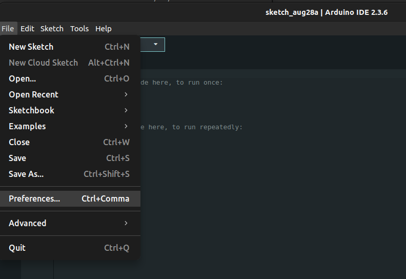
You need to copy and paste the following text to add the board package URL:
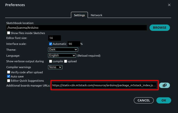
Once the board package URL has been configured, you can install it from the Boards Manager.
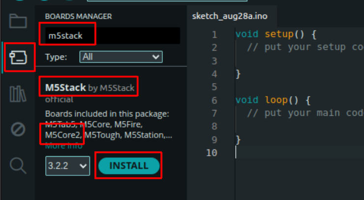
Tip
Updated instructions for installing the M5Core2 can be found here.
Warning
Please be aware of the recent updates to the ESP32 Core library for Arduino. In 2024, the Arduino-ESP32 core was upgraded from version 2.x (based on ESP-IDF 4.4) to version 3.x (based on ESP-IDF 5.1). The underlying API and build system changed some behaviors. Much of the code you may find online was written for the older 2.x version. All the lab sessions and programs in this course have been updated to the most recent version. More information about versions 2.x and 3.x can be found here.
Once installed, you can select M5Core2 from the board selection menu.
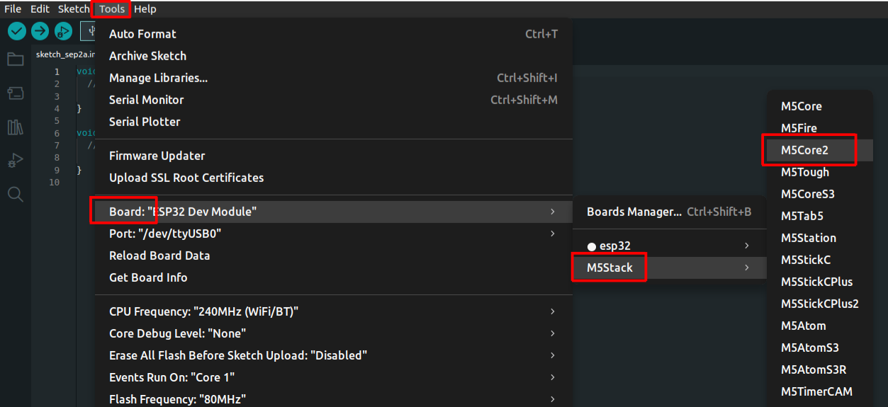
-
Install the Arduino libraries for M5Core2:
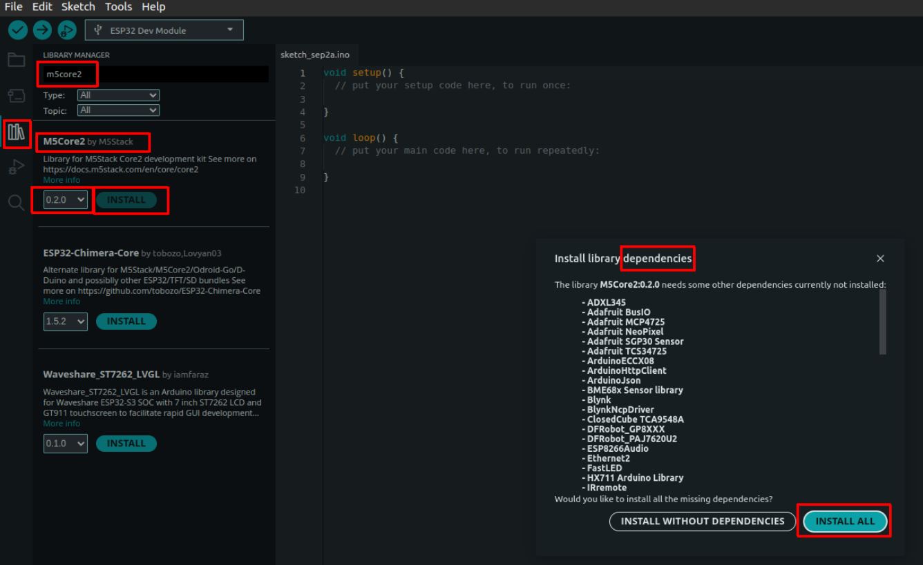
Warning
When you click Install, you will see a list of dependencies. You must install all of them as well.
Danger
If you encounter the following error during installation, it means that you do not have write permission for the library folder:
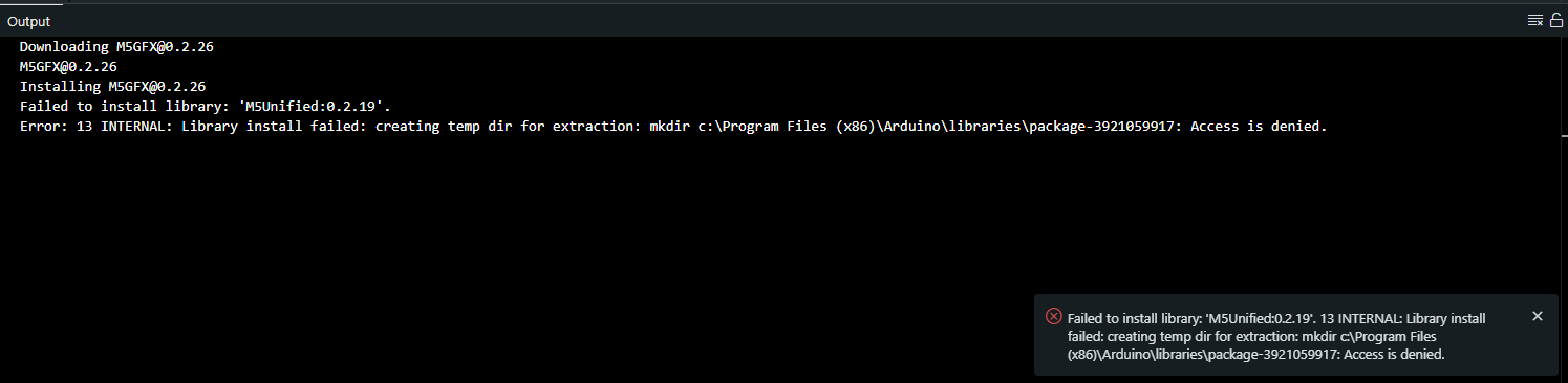
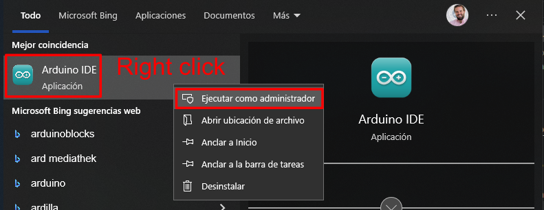
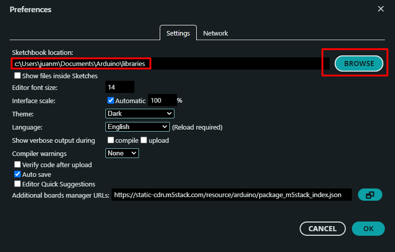
You can solve this problem in one of two ways:
-
Open the Arduino IDE as an administrator:
-
Change the library folder to a location where you have write permission:
-
-
Install the CP2104 USB driver:
Download it from one of the following links:
- Windows (Unzip the file and runCP210xVCPInstaller_Win7_v5.40.24.exe.) - macOS (Unzip the file and openSiLabsUSBDriverDisk.dmg.) - Linux (Unzip the file and follow the build instructions inCP210x_VCP_Linux_4.x_Release_Notes.txt.)More information about USB driver installation can be found here.
Now, when you connect the M5Core2 to the PC with the USB cable, you can select the port in the Arduino IDE.
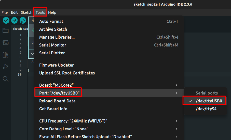
Info
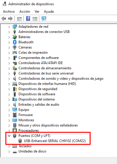
- On Windows, the port is named COMX, where X is a number that may vary, for example COM5.
- On Linux, the port is named ttyUSBX or ttyACMX, where X is a number that may vary, for example ttyUSB2.
Warning
If you see several devices and are not sure which one is the M5Core2, you can try one of the following:
- Connect and disconnect the device and check which device appears and disappears from the list. Note that to update the list of connected devices, you need to close and reopen the
Toolsmenu in the Arduino IDE. -
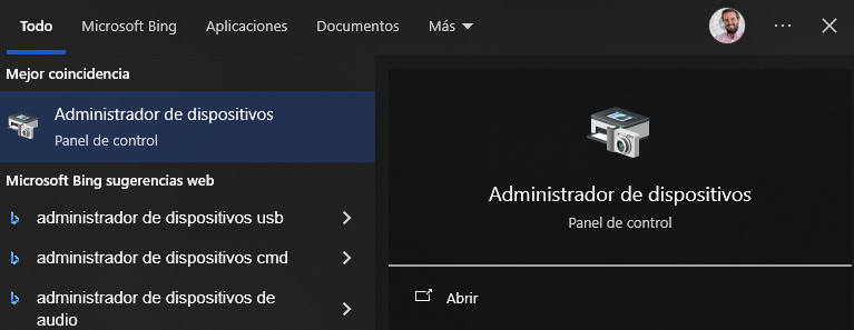
Check the connected devices in the Device Manager:
Note
You also need to select the correct board, as in step 2. Remember that you should always verify the board and port before uploading a program to the device.
-
Compile and upload the
hello_world.inoexample:#include <M5Unified.h> void setup() { // Initialize M5Core2. M5.begin(); // Print to the LCD screen. M5.Display.print("Hello World"); } void loop() { }Note
The first time you compile a program for the M5Core2, it may take some time.
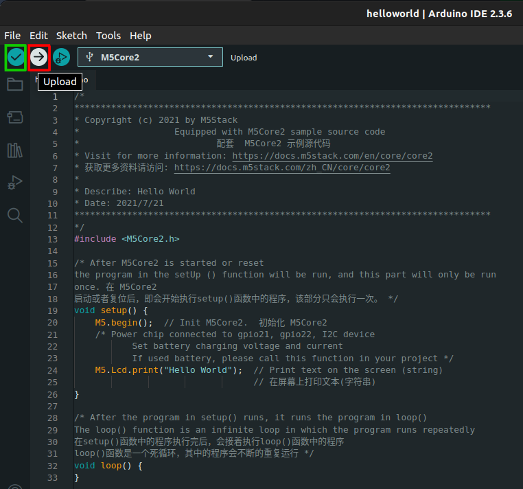
You can press the Upload button (red) to compile and upload the program to the device. Note that the Verify button (green) compiles the program but does not upload it.
Additional resources
You can find more documentation about some of the basic functions of the M5Core2 here.
Pinout and Important Notes
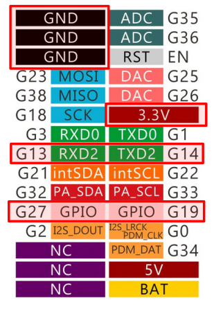
Below is the M5Core2 pinout. The pins marked in red are the ones we will use in the exercises.
Warning
- Some pins on the M5Core2 are preconfigured, so pay attention when connecting external components.
- The ESP32 inside the M5Core2 has three serial ports:
Serial1is reserved for the display (do not use it).Serial0can be configured (pinsG3 – RXD0andG1 – TXD0), but it is reserved for USB connection to the PC.Serial2is free and can be configured (pinsG13 – RXD2andG14 – TXD2) as regular GPIO usingpinMode().
1.2. Turn an LED On and Off
Connect an LED as shown below:
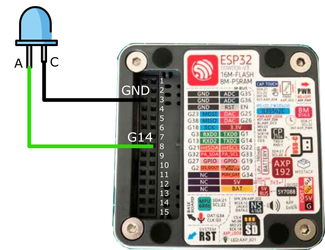
Run the following program:
#include <M5Unified.h>
#define LED_PIN 14

void setup() {
  M5.begin(); // Initialize M5Core2
  pinMode(LED_PIN, OUTPUT);
}

void loop() {
  digitalWrite(LED_PIN, HIGH);
  delay(500);
  digitalWrite(LED_PIN, LOW);
  delay(500);
}
Question
- What does the
#definedirective do? - What does the
pinMode()function do? - What does the
digitalWrite()function do?
Question
Note that you had to include the #include <M5Unified.h> line and the M5.begin(); // Initialize M5Core2 statement.
Why did you need to do that? What are these instructions for?
1.3. Additional Exercises
1.3.1. Blink at a Certain Frequency
-
Using the same circuit as in the previous exercise, write a program that blinks the LED at a frequency of 10 Hz.
Question
- How long should the LED remain on or off during each cycle?
1.3.2. Blink and Stop
-
Using the same circuit as in the previous exercise, write a program that blinks the LED at a frequency of 2 Hz and stops blinking after 5 seconds.
Question
- How many times does the LED blink?
- What is the final state of the LED when blinking stops: does it remain on or off?
2. Working in Simulation
2.1. Microcontroller Simulation
Launch an Example
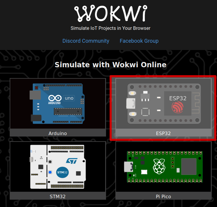
- Access the Wokwi simulation environment via this link.
-
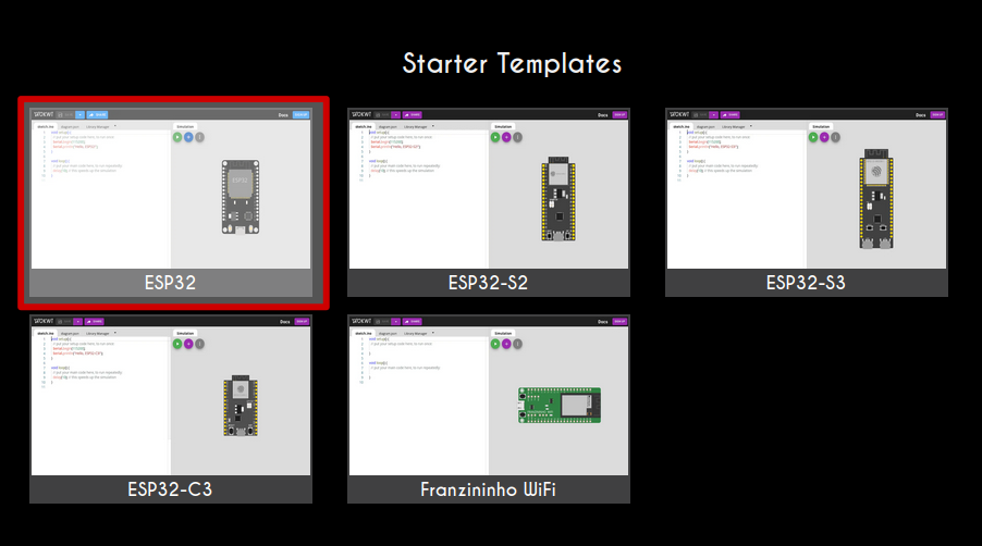
Select the ESP32 template.
Warning
Open the ESP32 template from
Starter Templates, not fromESP-IDF Templates. The former is based on the Arduino IDE, while the latter is based on the ESP-IDF environment, which will not be used in this course. -
Simulate the example program:
void setup() {
// Put your setup code here, to run once:
Serial.begin(115200);
Serial.println("Hello, ESP32!");
}

void loop() {
// Put your main code here, to run repeatedly:
delay(10); // This speeds up the simulation.
}
Warning
Here you are simulating the behavior of the system. Wokwi compiles the program and runs the resulting code in a virtual model of the microcontroller. Therefore, the code must be compilable for the simulation to run.
Info
- Note that the real-time factor in the top-right corner should be as close as possible to 100%. This value is a simulation performance metric. The closer it gets to 100%, the better the simulation. A value of 100% means the simulation is running in real time. If the value drops, the timing in the simulation is no longer reliable.
- Note the instruction
delay(10); // This speeds up the simulation.Try commenting out this line and see what happens. What if you usedelay(1);ordelay(5);?
Add Hardware Components
-
First, check the
diagram.jsonfile. What information do you see there? -
Connect an LED to
GPIO 21with a resistor, as shown in the diagram (rotate the components withrand flip them withpif necessary).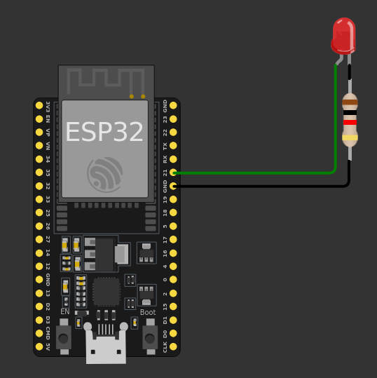
Question
- Check the
diagram.jsonagain. What happened? Can you change the color of the LED to green from this file? - What do you think you can do with the Library Manager?
- Check the
2.2. Turn an LED On and Off
Connect an LED as follows:
Run the following program:
#define LED_PIN 21
#define BUTTON_PIN 35

void setup() {
    pinMode(LED_PIN, OUTPUT);
    pinMode(BUTTON_PIN, INPUT_PULLUP);
}

void loop() {
    digitalWrite(LED_PIN, HIGH);
    delay(500);
    digitalWrite(LED_PIN, LOW);
    delay(500);
}
2.3. Control the LED State with a Push Button
-
Implement the circuit shown in the following diagram and write a program that:
- Turns the LED on when the button is pressed.
- Turns the LED off when the button is not pressed.
Tip
- Use the
digitalRead()function to read the status of the button. - You may need to use the
if...elsecondition.
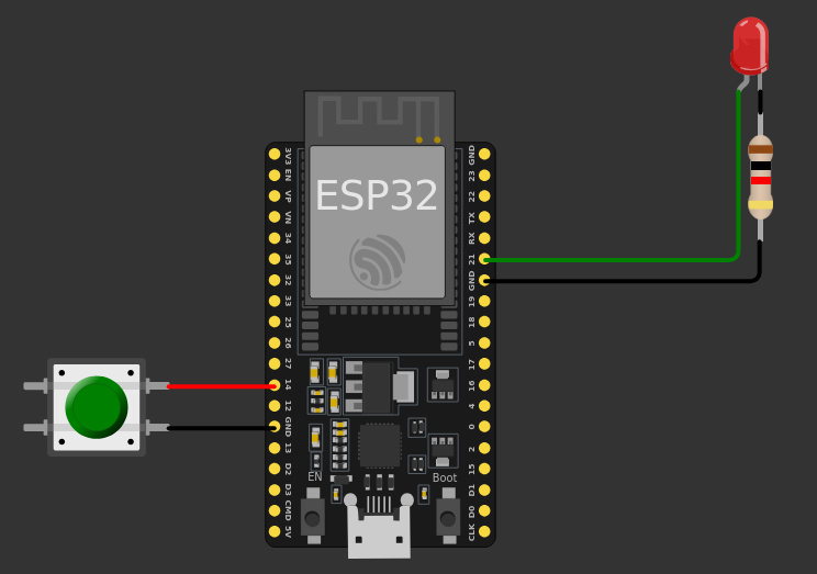
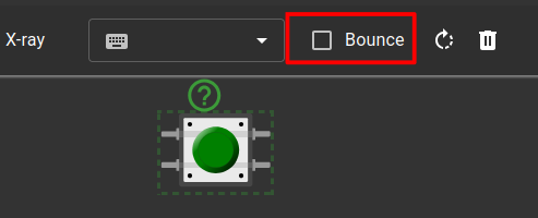
Warning
When you place the button, do not forget to deselect the bounce option to avoid contact bounce.
Question
- What information is included in the
diagram.jsonfile? Did it change compared to the previous exercise? - Can you complete the exercise without using the
if...elsecondition? How?
2.4. Additional Exercises
2.4.1. Blink
-
Using the same circuit as in the previous exercise, write a program that blinks the LED while the button is pressed.
Tip
You may need to use the
millis()function.
2.4.2. Short Press vs. Long Press
-
Using the same circuit as in the previous exercise, write a program that does the following:
- Short press (< 500 ms): toggle the LED (if the LED is on, turn it off, and vice versa).
- Long press (≥ 500 ms): blink the LED.