Lab Session 3: PWM
Estimated time: 1.5 hours (1 session)
Description
The goal of this lab session is to understand the generation and use of PWM signals, as well as how to control a DC motor using these signals. For this lab, you will need a DC motor, an L298N-based motor driver, and an M5Core2.
1. Working with real hardware
Part 1: Generating PWM with an LED
Generate a PWM signal to vary the brightness of an LED connected to GPIO14 of the M5Core2. You can check the Cheat Sheet for coding information.
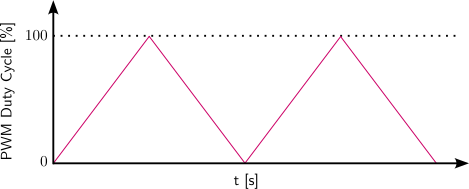
The LED must smoothly increase in brightness from completely off (a PWM duty cycle of 0%) to fully on (a duty cycle of 100%). Once it reaches 100%, it must smoothly dim back down to a duty cycle of 0%. Both the rising and falling phases should follow a "ramp" profile, like the one shown in the figure below:
Part 2: Generating PWM for a DC motor
The image below shows the connector layout of the motor driver:
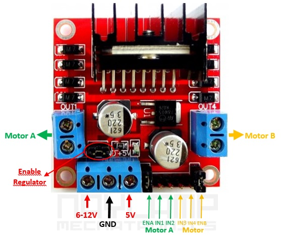
This driver can control up to two DC motors simultaneously. In the image above, the green ports correspond to motor A and the yellow ports to motor B.
Wire the M5Core2 to the L298N motor driver as follows:
- Connect
GPIO14toIN1on the driver. This PWM output will control the power in the positive rotation direction (counterclockwise). - Connect
GPIO13toIN2on the driver. This PWM output will control the power in the negative rotation direction (clockwise). - Connect
VSon the driver to the positive terminal of a 9–12 V power supply andGNDto its negative terminal. - Connect
GND(M5Core2) toGND(driver). It is essential to share grounds; otherwise the PWM signal reference is undefined. - Connect the motor to the motor A terminals on the driver.
- Ensure that the
ENApin on the driver is powered/enabled; otherwise, the motor A output will be disabled. Use the jumper to powerENAfrom the driver's onboard 5 V regulator.
A simple tutorial on using this driver can be found here.
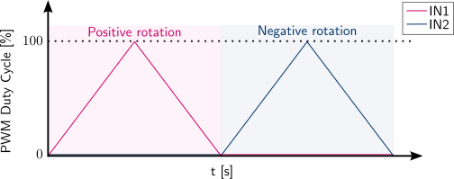
After wiring the microcontroller to the motor, modify the tutorial code so that the motor accelerates in the positive direction from a PWM duty cycle of 0% to 100%, then decelerates from 100% back to 0%. After completing the acceleration and deceleration in the positive direction, repeat the same sequence in the negative direction, and then loop this sequence indefinitely. The profile should be similar to the following image:
Question
- What happens when the PWM frequency is changed? Test frequencies between 1 kHz and 10 kHz.
- What happens when the PWM resolution is changed? Test resolutions between 8 and 10 bits.
- If the resolution is changed, is any other code change required or is it sufficient to update the resolution value?
2. Working in simulation
Part 1: Generating PWM with an LED
This exercise can be performed in simulation in the same way as on real hardware.
Part 2: Generating PWM for a DC motor
This exercise cannot be performed exactly the same way in simulation because Wokwi does not include a DC motor component. However, there are ways to prototype motor code in simulation.
A simple approach is to use two LEDs: LED 1 simulates the motor behavior when rotating clockwise, and LED 2 simulates rotation counterclockwise. Program the PWM signals for both LEDs in the same way you would for IN1 and IN2 on the driver. This lets you validate the PWM logic that will be used for the real motor.
Info
- To verify correct operation, ensure that the two LEDs are never on at the same time.
Tip
- When using PWM in Wokwi, real-time performance may degrade significantly if many PWM updates occur during each loop iteration. To avoid this, change the duty cycle in steps every few loop iterations or add a sufficiently long delay between updates. In other words, use a step-like signal instead of a ramp-like signal.